

Diagram for wiring ammeter & voltmeter
-
bdailjr
- Just Enlisted
- Posts: 11
- Joined: Sun Mar 04, 2012 1:19 pm
- Sailboat: MacGregor 26M
- Location: Knoxville TN 37918
Diagram for wiring ammeter & voltmeter
Looking for diagram for wiring an ammeter and voltmeter in order to monitor battery usage. I presently have the perko three position switch and a quest charger5/5 used with two 12v batteries. There was a thread back in 2010-03-28 in the mod section of the foram. Does anyone have a diagram for installing this type of monitoring system?
-
Catigale

- Site Admin
- Posts: 10421
- Joined: Fri Jun 11, 2004 5:59 pm
- Sailboat: MacGregor 26X
- Location: Admiral .............Catigale 2002X.......Lots of Harpoon Hobie 16 Skiffs....Island 17
- Contact:
Re: Diagram for wiring ammeter & voltmeter
The voltmeter is simple enough, positive to the pos on the Perko and negative to the neg. You will have to switch the Perko to measure each battery of course, and when on "BOTH" position both you will measure the voltage of the higher potential battery only.
The ammeter is more subtle. You probably want this in the main feed to the electrical panel, but realize that you won't measure the engine current this way., it isn't practical to measure this since your ammeter probably doesn't have the range to measure the 100 Amps + of starting current....ammeter goes in series of course,
The ammeter is more subtle. You probably want this in the main feed to the electrical panel, but realize that you won't measure the engine current this way., it isn't practical to measure this since your ammeter probably doesn't have the range to measure the 100 Amps + of starting current....ammeter goes in series of course,
-
Sumner

- Admiral
- Posts: 2375
- Joined: Sun Jan 04, 2009 3:20 pm
- Sailboat: MacGregor 26S
- Location: SE Utah
- Contact:
Re: Diagram for wiring ammeter & voltmeter
Not sure what kind of amp meter you have, but I would strongly recommend not using one where the full current is flowing through the amp meter like on an old car. These just aren't safe. You need to use one...
http://www.solarblvd.com/Solar-Meters-A ... _info.html
...that uses a shunt and with it wired in you can see what the amps are. You choose a shunt based on total draw. Not sure what amp draw there is on your guys outboards, but if it is below 100 amps the amp meter above would work to 1/10th amp with a 100 amp shunt.
You run all negative loads through the shunt before the negative side of the battery/barreries. If you don't want the outboard amps then bypass the shunt with the negative from the outboard. The amp meter will have instructions on wiring the shunt. We use the above on the Mac and love it,
Sum
-
mastreb

- Admiral
- Posts: 3927
- Joined: Wed Feb 09, 2011 9:00 am
- Sailboat: MacGregor 26M
- Location: Cardiff by the Sea, CA ETEC-60 "Luna Sea"
- Contact:
Re: Diagram for wiring ammeter & voltmeter
You might consider using a non-contact clamp-type ammeter so you don't need to deal with the wiring. Or forgoing an ammeter altogether--Voltage drop will tell you when a battery is low, so I see little need for an ammeter.
-
chipveres
- Engineer
- Posts: 170
- Joined: Sat Aug 11, 2012 12:53 pm
- Sailboat: MacGregor 22
- Location: Dania, FL
Re: Diagram for wiring ammeter & voltmeter
To answer Benny's question, my first choice in a clamp-on meter is Amprobe. They are the original manufacturer. Just be sure to get one suitable for DC, as the older units are AC only.
For meters that are wired up permanantly, look at Blue Seas Systems or Ancor.
Chip
S/V Macaroon
Dania, FL
For meters that are wired up permanantly, look at Blue Seas Systems or Ancor.
Chip
S/V Macaroon
Dania, FL

Re: Diagram for wiring ammeter & voltmeter
Not sure what kind of amp meter you have, but I would strongly recommend not using one where the full current is flowing through the amp meter like on an old car. These just aren't safe.
Sum
Sum what do you think of the RC "Watts UP" type of meters? They are supposed to keep track V/A/W being used and also Wh and Ah used over time. Seems overkill for what I need, but has some good reviews by people using it on solar systems. If I rember right some people are running two keeping track of both Ah in and out of their systems.

http://www.amazon.com/gp/product/B001B6 ... SJ3SRDH3BD
-
Sea Wind

- First Officer
- Posts: 402
- Joined: Mon Mar 28, 2011 9:45 am
- Sailboat: MacGregor 26X
- Location: Mayo, MD Suzuki DF90hp
Re: Diagram for wiring ammeter & voltmeter
Here you go. Click on the pdf link. This is for a digital multimeter (volt and amp meter) with a shunt.
http://bluesea.com/viewresource/81
I have this unit and I strongly recommend it.
Pedro
http://bluesea.com/viewresource/81
I have this unit and I strongly recommend it.
Pedro
-
Boblee
- Admiral
- Posts: 1702
- Joined: Thu Aug 10, 2006 5:08 am
- Location: Berrigan, Riverina Australia boatless at present
Re: Diagram for wiring ammeter & voltmeter
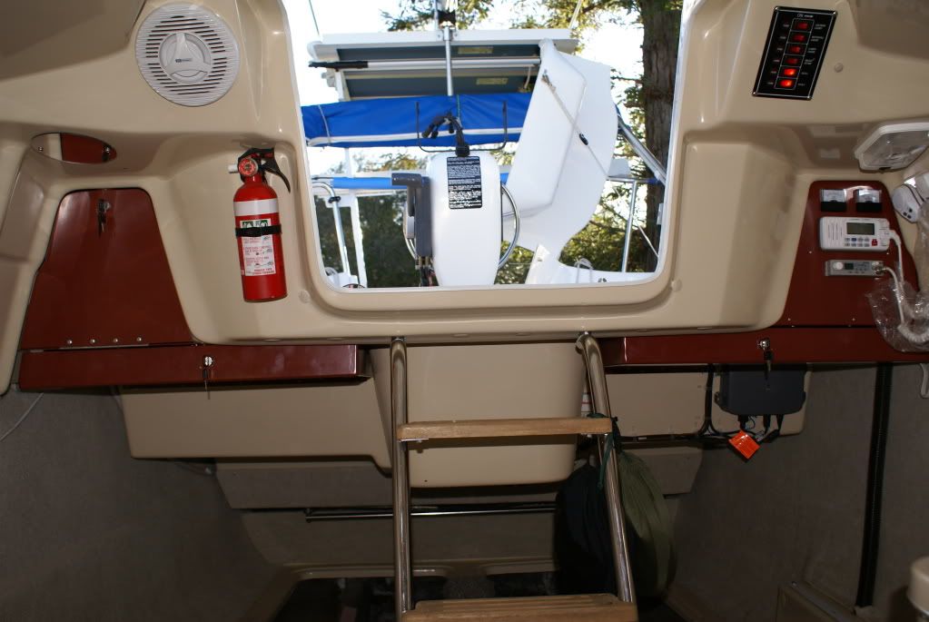
The only voltage and amps I am interested in are the draw and voltage of the general light and power circuits and navigation gear in the boat so have the voltmeter across the lines feeding the fuseboard and the ammeter on the incoming line, they are installed as in the photo but possibly could be mounted beside the original fuseboard.
We do have a solar regulator which does give voltage at the battery but the amps used side is not hooked up to any circuits but don't seem to have a photo of it installed in front of the battery compartment under the steps.
We do have a solar regulator which does give voltage at the battery but the amps used side is not hooked up to any circuits but don't seem to have a photo of it installed in front of the battery compartment under the steps.
-
Sumner
- Admiral
- Posts: 2375
- Joined: Sun Jan 04, 2009 3:20 pm
- Sailboat: MacGregor 26S
- Location: SE Utah
- Contact:
Re: Diagram for wiring ammeter & voltmeter
Personally I would also only want to use something with a shunt for the amp reading like the unit above that Pedro mentioned or others that are out there. Running amps through a gauge is not the safest thing to do as it will be carrying all of the amps through that gauge and the wire to and from it. Using a shunt is much safer. Not sure exactly how that unit on Amazon works but I probably wouldn't buy it (just a gut feeling).Sea Wind wrote:Here you go. Click on the pdf link. This is for a digital multimeter (volt and amp meter) with a shunt.
http://bluesea.com/viewresource/81
I have this unit and I strongly recommend it.
Pedro
We run a volt meter and an ammeter (with a shunt on the Mac)....
http://purplesagetradingpost.com/sumner ... de-25.html
The Endeavour has an older ...
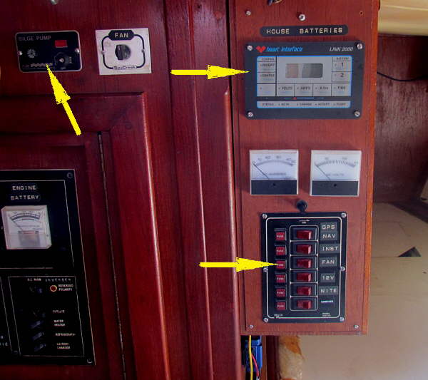
... Link 2000 (top right arrow) that can read two different battery banks and also keep track of the watt usage. We will continue to use it for a while, but I'm also adding a second volt meter like is on the Mac that I can check voltage on either battery bank via a switch. I'm also putting an ammeter like on the Mac on the house loads (not the starter and such) so I can see what they are individually by turning only one thing on at a time. I really don't trust the Link 2000 anymore and the gauges below it are no longer in use. That is where I'll put the new ones.
Eventually I'd like us to get a Blue Sky IPN Pro Remote...

http://www.blueskyenergyinc.com/product ... _proremote
...as it will do everything the Link 2000 will do plus more like controlling the .....
...solar panel charge controller better,
Sum
===================================
Our MacGregor 26-S
Our Endeavour 37
Our Trips to Utah, Idaho, Canada, Florida
Mac-Venture Links
-
kurz

- Admiral
- Posts: 1304
- Joined: Mon Dec 06, 2010 9:07 am
- Sailboat: MacGregor 26M
- Location: Zürich, Switzerland, Europe
Re: Diagram for wiring ammeter & voltmeter
how about the voltmeter in the Motorpanel at the helm?
I have an merc 60hp efi, and it shows all temps but also volts.
My question: Can I let the "iginition on", so that the display is on, but the motor stays off.
Does this situation takes energy of the battery? Or can it harm the motor if it would be on whole day without motor on?
I have an merc 60hp efi, and it shows all temps but also volts.
My question: Can I let the "iginition on", so that the display is on, but the motor stays off.
Does this situation takes energy of the battery? Or can it harm the motor if it would be on whole day without motor on?
-
mastreb
- Admiral
- Posts: 3927
- Joined: Wed Feb 09, 2011 9:00 am
- Sailboat: MacGregor 26M
- Location: Cardiff by the Sea, CA ETEC-60 "Luna Sea"
- Contact:
Re: Diagram for wiring ammeter & voltmeter
I use a binary power sensor:
1) Motor starts = Voltage and amperage sufficient
2) Motor doesn't start = Voltage and amperage insufficient.
Tells me everything I need to know
1) Motor starts = Voltage and amperage sufficient
2) Motor doesn't start = Voltage and amperage insufficient.
Tells me everything I need to know