Hi All!
It’s been a month of slow steady progress getting Over Easy ready for the 2022 season (after a slow delayed start….but that’s water under the bridge

).
So far we have removed the old 2001 vintage 50 hp Tohatsu 2-stroke engine and stripped out the related engine controls and cables. The portable engine hoist/crane was a great choice allowing for one person removal and movement to temporary storage in the garage. (More about it’s future at a later date

).
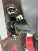
We pulled the side panels on the pedestal to gain access to remove the engine cables and wires. Well that didn’t go as easily as anticipated

. The “Well Nuts” we installed last year bound up and just spun int the fiberglass even though we had used 5200 to bed them in and applied Teflon to the threads. Felt like Monkey with a coconut

through a picket fence as the problem occurred on most of the fasteners on both sides

effectively locking them on! With lots of gentle persuasion and much more time than anticipated the panels were finally removed without damaging the panels or pedestal. Post Mortum showed the brass thread inserts of the rubber sheathed “Well Nuts” had corroded jamming the threads. Won’t be doing that again!!!

The next fix for this is going to be mixing up some fiber glass “hair” epoxy filler and plugging the holes in the pedestal then drilling new pilot holes for new SST screws. More work….
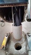
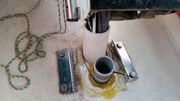
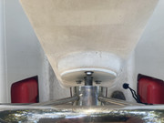
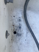
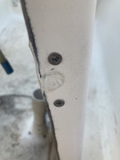
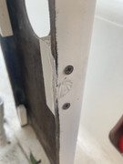
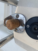
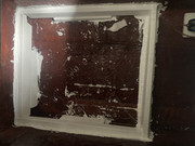
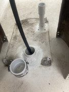
While having to unbolt the pedestal from the cockpit floor I decided that while the cables were removed it was a prime time to investigate the persistent nuisance leak into the aft berth I’ve suspected originates at the two pedestal feed throughs. It appears that at sometime in the past (from factory?) the larger 2” feed thru had a piece of PVC pipe inserted through the cockpit floor but not through the aft berth head liner. This allowed it to cock to one side in the interspace slightly. The silicone sealant applied minimally at the cockpit floor cracked through allowing water to migrate into the interspace and into the aft berth and on back to the engine bowl head liner void.
The second existing (Factory? PO?) feed thru was a 1-1/2 dia hole through the cockpit floor and aft berth head liner without a sleeve pipe. A plastic boot was screwed to the cockpit floor. Removal of the boot showed that sealant was not fully applied to the floor interface and what had been applied was done to a dirty floor surface. This also had been allowing water to migrate into the aft berth and interspace and on back to the engine bowl.
These migration leak locations could very well explain the aft berth leaks and the fracturing of the inner head liner of the engine bowl and water leakage at the bottom lip flange of the bowl liner!
The fix done was to get the feed troughs cleaned up to remove ALL trace of ANY old silicone sealant.
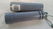
— then get the existing PVC sleeve to go all the way through the inner head liner
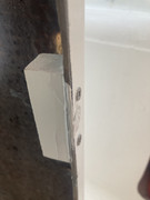
— a new PVC sleeve with a 6” riser was added to the second feed through hole of the cockpit deck and aft berth headliner
— these were then throughly wetted and bedded with 5200 sealant with a generous overlay at both the cockpit floor and aft berth head liner interfaces after a through cleaning, scuffing and acetone wipe down.
— an extension was added to the larger PVC sleeve to increase the opening height above the cockpit floor as well.
Hopefully this will eliminate these nuisance leaks!!!

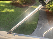
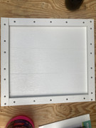
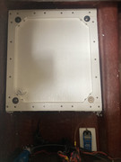
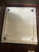
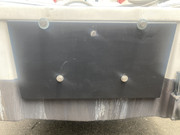
The new 3/4” thick G-10 transom reinforcement plate was cut to size, drilled, edge routered both sides, primed and coated with anti fouling paint. It was then mounted to the transom aft face with sealing washers (sealed with 5200 on both contact faces) and bolted in position with the engine mount bolts to cure. A separate retention bolt was added so that the new reinforcement plate will stay in position and not drop out whenever the engine mount bolts are removed ( like when our new engine is installed.
{Note of Interest: With the opportunity to work on the transom intimately I discovered that the as built Mac26X factory transom is rather limited. The glassed in reinforcement appears to be two sections of plywood… the section most aft appears to be 12x18x1/2” thick…the section in front of that appears to be 12x12x3/4” thick…It’s hard to tell the exact thickness but the width and height are pretty close. This may help substantiate why MacGregor recommended the engine size he did…. Just passing it along

.}
Our additional 3/4 thick G-10 fiberglass reinforcement & load distribution plate is 23-1/2” wide and 12” tall. This should be more than adequate to help manage the additional thrust loads of our new engine installation.
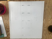
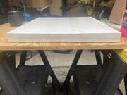
We are also upgrading our cabin bed cushions for the Vee-Berth and Dinette-Berths to 7” thick mattress foam! We have cut and trimmed the sections to fit.

SO MUCH MORE COMFORTABLE THAN THE OLD FACTORY PADS
!!!
We will be making (or have made) the Sunbrella covers later as well as adding air-gap underlayment once we get North. For now we will just wrap the sections in flat sheets for our trip North.
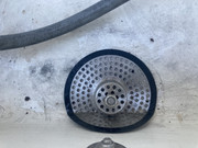
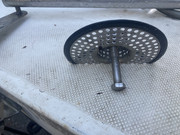
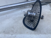
The improved larger size interior through the hull sonar transducer mount is completed, the porous foam fitted, filled with 3 gallons of RV antifreeze and sealed! Finally! The new tank uses the three existing surfaces of the under aft dinette seat area. When the ballast is flooded and the boat is in the water the areas opposite these surfaces are wetted areas. The box is fabricated from PVC lumber, SST screws and 5200 adhesive. All surfaces were throughly scuffed and cleaned with Acetone. No punctures were made in the interior hull liner. The new sonar transducer tank spans the distance from the keel trunk side over to the Starboard water ballast transfer tube which is about 18 inches. The forward portion abuts the water ballast tank aft wall under the forward dinette seat and goes aft about 19 inches. The depth of the tank varies with the slope of the hull and is deepest by the keel trunk (~5 inches) and shallowest by the ballast transfer tube (~3 inches). The transducer I’d suspended in saturated foam at about 1 inch above the interior hull and level fore-aft and side-to-side. We’re hoping when the water ballast is fully flooded that this should give us good depth readings and allow us to use the side scan feature of our Garmin Chartplotter system. Next step is to test it once we are on the water up North…


Our target is to get on the road North by this coming Tuesday morning via Vermont to watch our older daughter participate in a 10k (6 mile) Open Water Swim at Lake Memohremagog starting at Prouty Beach in Newport Vt. Then on to NH to get our new engine installed the first week of August!
Best Regards
Over Easy


 ).
).  . The “Well Nuts” we installed last year bound up and just spun int the fiberglass even though we had used 5200 to bed them in and applied Teflon to the threads. Felt like Monkey with a coconut
  through a picket fence as the problem occurred on most of the fasteners on both sides
 effectively locking them on! With lots of gentle persuasion and much more time than anticipated the panels were finally removed without damaging the panels or pedestal. Post Mortum showed the brass thread inserts of the rubber sheathed “Well Nuts” had corroded jamming the threads. Won’t be doing that again!!!
 .}
.} SO MUCH MORE COMFORTABLE THAN THE OLD FACTORY PADS