Page 1 of 3
rudder uphaul lever
Posted: Mon Jun 16, 2014 8:53 pm
by DaveC426913
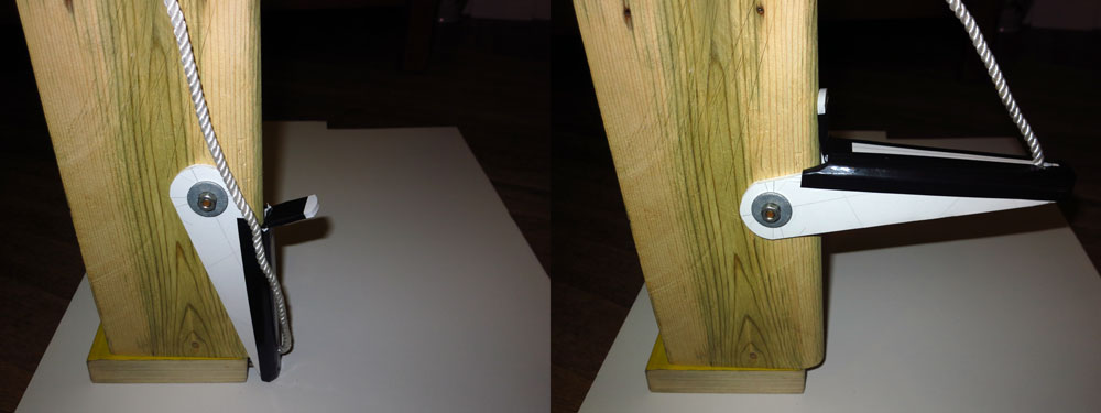
Finished my prototype! Made of foamcore and held in shape with elec. tape.
That block of wood is an accurate rendition of the relevant part of my

rudder. (in 'down' position, trailing edge on right)
Now to find a stainless steel bender...
Re: rudder uphaul lever
Posted: Mon Jun 16, 2014 10:22 pm
by Boblee
Any metal fabrication shop should be able to bend it for you but personally would just do it in a vice with a hammer.
BTW what are you trying to accomplish with the lever?
Re: rudder uphaul lever
Posted: Tue Jun 17, 2014 4:38 pm
by DaveC426913
Boblee wrote:Any metal fabrication shop should be able to bend it for you but personally would just do it in a vice with a hammer.
Yeah, I'm in talks with one or two.
No way I'm doin it with a hammer. They'd look like I'd backed into a pier 600 times. I'd be a laughing stock.

Boblee wrote:BTW what are you trying to accomplish with the lever?
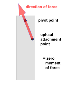
Better leverage in lifting them, esp. while underway (sail > power)
My lines run right across the pivot point, so leverage is almost zero.
That equates to only one person on the boat strong enough to lift them, and one's on the helm. Admiral gets antsy when I fiddle with the rudders. Pointy end of the boat tends to head for the nearest rock.
Re: rudder uphaul lever
Posted: Tue Jun 17, 2014 5:24 pm
by seahouse
Looks good Dave. I've dealt with Bayview Metals (I think they're up your way) in the past with stainless fabrication. A simple CAD drawing will make things easy with that too, if you haven't already.
B.

Re: rudder uphaul lever
Posted: Tue Jun 17, 2014 8:44 pm
by DaveC426913
seahouse wrote:Looks good Dave. I've dealt with Bayview Metals (I think they're up your way) in the past with stainless fabrication.
Thanks. I will check them out.
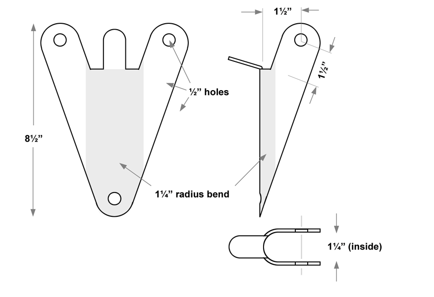
Note to self: ensure you label this diagram as a
sketch. Exact configuration to be determined later (after I figure out what bends in thick steel do to dimensions)
Re: rudder uphaul lever
Posted: Tue Jun 17, 2014 10:18 pm
by seahouse
I'm a little rusty, but I used to do cold bend calculations regularly. During a bend, half the thickness of the metal "compresses" (the inside) and the other half stretches (the outside). Except it's not half. It's about 40% of the thickness of the material, closer to the inside, where the "neutral" bend line is, which is where the metal neither stretches nor "compresses". (Note the quotes)

.
This info might help get you closer, Dave. But you are right, bending a sample of the material you will be using will get you right on the money, but the part is not to fussy tolerances and the fabricators will know how to get you there.
- B.
PS. A quick and dirty trick
I used to use (and you might too) to confirm ballpark calculations was to make an equivalently-dimensioned piece out of marked-in-increments plasticene, and form it, being careful not to stretch or compress it as you do. Not the whole part of course, but just a section of the area to be bent.
BTW - your bend radius will be 5/8" for an inside 1- 1/4". (a typo).
Re: rudder uphaul lever
Posted: Tue Jun 17, 2014 10:29 pm
by Highlander
Why not just add a few cheep blocks & make a 2-1 or even a 3-1 pulley system
J
Re: rudder uphaul lever
Posted: Tue Jun 17, 2014 10:45 pm
by seahouse
Yes, I agree, J.
The advantage of the blocks you're suggesting is that the force-multiplying happens throughout the uphaul arc. With the levers we're discussing however, you gradually lose the mechanical advantage as the rudder moves through the arc as it is raised, as it eventually becomes zero.
B.
Re: rudder uphaul lever
Posted: Wed Jun 18, 2014 12:25 am
by Highlander
here's what i done not the best view but gives u some ideal
http://s844.photobucket.com/user/TheHig ... 1.mp4.html
J
Re: rudder uphaul lever
Posted: Wed Jun 18, 2014 6:38 am
by DaveC426913
seahouse wrote:I'm a little rusty, but I used to do cold bend calculations regularly. During a bend, half the thickness of the metal "compresses" (the inside) and the other half stretches (the outside). Except it's not half. It's about 40% of the thickness of the material, closer to the inside, where the "neutral" bend line is, which is where the metal neither stretches nor "compresses". (Note the quotes)
.
Thanks! That's precisely what I'm grappling with right now. If I give them flat dimensions and expect them to bend into a 3D form, I have to know the thickness of the material as well as how it compresses/expands when it bends - or my final piece will come up short. Your explanation is exactly what I need to know (and my intuition, as someone who was never in the biz, is correct).
In my foamcore template, it bent on the inside surface (the ... kerf cuts? ... are on the outside), so all expansion, no compression - that's why I had to reinforce it with elec. tape. But I knew metal wouldn't behave that way.
seahouse wrote:
BTW - your bend radius will be 5/8" for an inside 1- 1/4". (a typo).
D'oh. Of course.

Re: rudder uphaul lever
Posted: Wed Jun 18, 2014 6:40 am
by Boblee
Highlander wrote:Why not just add a few cheep blocks & make a 2-1 or even a 3-1 pulley system
J
Yep they come up easy peasy on the

and so does the dagger board.
Re: rudder uphaul lever
Posted: Wed Jun 18, 2014 6:43 am
by DaveC426913
Highlander wrote:Why not just add a few cheep blocks & make a 2-1 or even a 3-1 pulley system
J
Because 2 x zero or 3 x zero is still zero.
Re: rudder uphaul lever
Posted: Wed Jun 18, 2014 6:45 am
by DaveC426913
seahouse wrote:Yes, I agree, J.
The advantage of the blocks you're suggesting is that the force-multiplying happens throughout the uphaul arc. With the levers we're discussing however, you gradually lose the mechanical advantage as the rudder moves through the arc as it is raised, as it eventually becomes zero.
B.
That is no problem at all. Once the rudders are above horizontal, there is no further need for mechanical advantage. The lifting "vector" is plenty far from the pivot point by then.
Re: rudder uphaul lever
Posted: Wed Jun 18, 2014 8:42 am
by Paulieb
That looks like a really cool idea. Nice diagrams too.
My only recommendation would be that the Tab that looks like it will rest up against the rudder when pulled up, looks like it might be a weak point.
I would consider adding a wedge shaped gusset to strengthen that point - there is likely to be a lot of stress there and metal fatigue.
Paul
Re: rudder uphaul lever
Posted: Wed Jun 18, 2014 8:56 am
by DaveC426913
Paulieb wrote:That looks like a really cool idea. Nice diagrams too.
My only recommendation would be that the Tab that looks like it will rest up against the rudder when pulled up, looks like it might be a weak point.
I would consider adding a wedge shaped gusset to strengthen that point - there is likely to be a lot of stress there and metal fatigue.
Paul
Yes. Thing is, because the tab probably will bend under load, there will likely end up being very little pressure on the middle or end of the tab; it will all be concentrated at the base (i.e. even if the tab were of zero length, it would likely still function). So I think it's strong enough to hold. My bigger concern is whether it digs into my rudder at that point.
I'm considering attaching a little U-shaped plate on the rudder itself to spread the load where the tab will brace against it.
That, and the fact that welding a wedge will complicate (=$$) the construction.