

Will recalculate The over current protection. As for shore power, yes at some point. At the least I’d like to run an extension cord and use a noco charger on the batteries. I’m not quite sure how to incorporate a loxkg shorepiwer plug into this system. Anyone know?
Thx!
Solar install - Check my work?
-
BOAT

- Admiral
- Posts: 4969
- Joined: Fri Oct 19, 2012 5:12 pm
- Sailboat: MacGregor 26M
- Location: Oceanside, CA MACMJ213 2013 ETEC60
Re: Solar install - Check my work?
Hey Chumpy,Chumpy36 wrote: ↑Sun Dec 25, 2022 3:21 pm Will recalculate The over current protection. As for shore power, yes at some point. At the least I’d like to run an extension cord and use a noco charger on the batteries. I’m not quite sure how to incorporate a loxkg shorepiwer plug into this system. Anyone know?
Thx!
You got the real pros like Jimmy and others out of the woodwork to help you - that's lucky - I always listen to those guys cuz they know what they are talking about.
I went through the whole solar thing when I updated my old Sprinter van and I had to add an entire separate system to handle lithium. The AC charger from shore power needs to be higher voltage too. When I realized how separate and different the two systems are (lithium vs. AGM) I decided I would NOT change 'boat' to lithium. I just decided to keep 'boat' an AGM system and got a solar generator and those thin folding portable solar panels I throw out on the deck when moored or at anchor. For me trying to run both systems on the boat was too much to deal with.
The other guys like Jimmy and Bill and the Canadian Captain know what they are talking about.
-
Starscream

- Admiral
- Posts: 1593
- Joined: Tue Nov 03, 2009 10:08 am
- Sailboat: MacGregor 26X
- Location: Montreal, Quebec. 2002 26X - Suzi DF90A
Re: Solar install - Check my work?
Shorepower is a relatively easy add. There are several ways to do it, from simple to complete.Chumpy36 wrote: ↑Sun Dec 25, 2022 3:21 pm Will recalculate The over current protection. As for shore power, yes at some point. At the least I’d like to run an extension cord and use a noco charger on the batteries. I’m not quite sure how to incorporate a loxkg shorepiwer plug into this system. Anyone know?
Thx!
A complete system starts with a shore power inlet, which are about 30 bucks on Amazon. Our inlet is on the port side behind the cabin side windows where the back of it is accessible through the main fuse panel cutout. Some have added it to the rear of the cockpit in the seat support posts, if you know what I mean. Then, a short length of marine grade wire runs to a 120V breaker panel I installed in the side of the galley structure, facing aft. The 120 V panel has breakers for our two 120V outlets in the cabin, one for the battery charger, and a spare. For the battery charger I just cut the plug off, stripped the wires, and hard-wired it to the breaker panel. The breaker panel includes a voltage indicator, which is nice because marina 120V outlets are gfci protected and nuisance trip a lot, and it's our only visible indicator of a power loss in the cabin, since the charger is under the galley.
A simpler version would be to buy the shore power inlet that has a 120V plug connector on the inside. Then just plug the battery charger directly into that and you have shore-based battery charging for less than $50 plus an hour or so of work.
I once had a dual bank charger, which was heavy but kept both batteries topped up individually. I changed that to a smaller single bank charger with an additional ACR relay. The ACR relay allows both batteries to charge if any charging voltage is present: alternator, solar, or charger. With the ACR, both batteries are always charging from any available source regardless of the battery selector position. It's super convenient because I never have to worry about which battery is charging at any given time; they will both charge together from any of the three onboard sources.
Chumpy, I posted my wiring diagram for you on FB, did you see it?
-
Chumpy36
- First Officer
- Posts: 245
- Joined: Thu Oct 27, 2022 7:54 pm
- Sailboat: MacGregor 26S
- Location: Atlanta
Re: Solar install - Check my work?
Thanks for that. May have more questions later when I get around to doing this. It’s lower down the list.
I don’t think I saw the diagram. What’s your name and I’ll search.
Thank you!
I don’t think I saw the diagram. What’s your name and I’ll search.
Thank you!
-
Be Free

- Admiral
- Posts: 1974
- Joined: Fri Nov 23, 2012 6:08 pm
- Sailboat: MacGregor 26X
- Location: Steinhatchee, FL
Re: Solar install - Check my work?
A simpler version would be to buy the shore power inlet that has a 120V plug connector on the inside. Then just plug the battery charger directly into that and you have shore-based battery charging for less than $50 plus an hour or so of work.
+1!
+1!
Bill
2001 26X Simple Interest
Honda BF40D
"If I were in a hurry I would not have bought a sailboat." Me
2001 26X Simple Interest
Honda BF40D
"If I were in a hurry I would not have bought a sailboat." Me
-
Starscream
- Admiral
- Posts: 1593
- Joined: Tue Nov 03, 2009 10:08 am
- Sailboat: MacGregor 26X
- Location: Montreal, Quebec. 2002 26X - Suzi DF90A
Re: Solar install - Check my work?
Here it is.
For the ACR, I never ended up installing the on/off switch with the 1-amp fuse, and I didn't wire the ACR ignition wire either. Neither are really necessary. The ACR never drew the batteries down over 6 months of winter, and with dual purpose batteries I'm not worried about pre-disconnecting them during a motor-start.
I've also added a second fuse panel on the starboard side, and I wired that directly off the battery with something like a 30Amp breaker, IIRC. The starboard panel runs the water system including the macerator pump, and that takes a bunch of amps when it runs.
I'm pretty sure I kept the two 50W solar panels in series, but I keep on meaning to check. They're mounted on the bimini top, and not shaded by anything other than the backstay when in our slip.
I have a 300W inverter that I plan on installing sometime next year. I'll have to research it's amp draw to determine if I put it on the fuse panel or wire it directly.
-
Ixneigh

- Admiral
- Posts: 2494
- Joined: Thu Sep 09, 2010 11:00 am
- Sailboat: MacGregor 26M
- Location: Key largo Florida
Re: Solar install - Check my work?
That looks awfully complicated. I just left the oem wiring system and put the solar onto the house battery. Had its own fuse and regulator. I can charge the starter battery by switching the selector to ALL. The starter batter has a small panel to trickle charge it. The dealer I talked a selector switch and additional battery. Everything else is stock.
Btw those panels ARE NOT 200 watt panels. I doubt they are even 100 each, if they are the flexible kind. Plus, the output drops off drastically if not facing the sun straight on. I bought one, I think they rate them at watts per DAY (in which case, accurately so)
I’ve never seen flexible panels that are all that great.
"Shoal Idea"
2011 M, white
Tohatsu 20
South Fl.
2011 M, white
Tohatsu 20
South Fl.
-
Chumpy36
- First Officer
- Posts: 245
- Joined: Thu Oct 27, 2022 7:54 pm
- Sailboat: MacGregor 26S
- Location: Atlanta
Re: Solar install - Check my work?
Yeah, there's no way they are 200. I suspect maybe 50 based on the size.
-
Chumpy36
- First Officer
- Posts: 245
- Joined: Thu Oct 27, 2022 7:54 pm
- Sailboat: MacGregor 26S
- Location: Atlanta
Re: Solar install - Check my work?
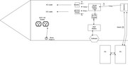
Ok, I've redone my diagram based on feedback here and other places. See attached. The last thing I need to understand is overcurrent protection.
So 10awg is supposed to be fused at 30amps as that's what the wire can support. My maximum current draw (if I have everything running at the same time) is 23.4 amps. There's no way that will happen as that includes both (eventual) bilge pumps, all lights, chargers, etc and the fridge going full blast.
So it seems I should fuse at the battery for 30amps right? I know I should have one between the inverter and the batter as well as the breaker panel and battery but if they are all connected directly to the battery doesn't the one 30amp fuse (breaker actually) I installed on the positive terminal of the battery protect both the breaker panel and the inverter? I also believe the inverter is internally fused as well.
Do I need breakers/fuse between the DC-DC charger? either between the start battery and the charger and the house battery and the charger?
Thanks again.
-
BOAT
- Admiral
- Posts: 4969
- Joined: Fri Oct 19, 2012 5:12 pm
- Sailboat: MacGregor 26M
- Location: Oceanside, CA MACMJ213 2013 ETEC60
Re: Solar install - Check my work?
Hey Chumpy,
I don't know where the other guys are - I have been waiting for them to review your drawing cuz they know the best. Not sure where they are.
It all looks pretty good to me but I think you should wait to see what they say cuz they are smarter than me. I would wonder if it's okay to attach the inverter output to the GFCI plugs but you better ask the guys because it might require a transfer switch.
-
Be Free
- Admiral
- Posts: 1974
- Joined: Fri Nov 23, 2012 6:08 pm
- Sailboat: MacGregor 26X
- Location: Steinhatchee, FL
Re: Solar install - Check my work?
How I Would Do It...
Size the wire between the controller and the battery so that it can carry the rated output of the controller. I'd go a bit higher to decrease voltage drop and for just because I don't like to push wiring near its limits. I usually aim for about 25% over so your 30 amp would be wired for 37.5 (round up as needed).
Fuse the wire between the controller and the battery to match the rated output of the controller. You don't need to add a safety margin to this one. The fuses will go before the wire. You are just "pulling the plug" if something goes horribly wrong with the controller.
I've seen disagreement as to whether or not there needs to be a fuse between the panels and the controller. Theoretically if you use wire that can handle the rated output of the panel(s) then a fuse is not needed. On the other hand, other than a very small voltage drop, the fuse will not cause any problems. Don't forget that if your panels are in parallel the voltage stays the same and the amperage is added, in series the voltage is added and the amperage remains the same.
You will most certainly want a fuse between the battery and the inverter. The fuse would be ContinuousWatts/NominalDCVoltage then add a 25% safety margin. Size the wire to carry the full current that the fuse will take plus another 25% (because I don't like to push the limits). NominalDCVoltage is at the inverter, not at the battery. You will have voltage drop in the wire. Consider that to be the smallest wire you can run. Bigger and shorter wire is almost always better. You will have less voltage drop and your inverter will be happier.
The wire between the batteries and the DC-DC charger should be sized to carry the rated output of the charger (+25%). Each side should be fused to the rated output of the charger.
There is not normally a fuse between the outboard and the start battery (and ABYC does not require it). The cable to the outboard is normally sized appropriately. However if the cable is shorted you will melt it and may set your boat on fire. I'm of the opinion that it is unlikely that you will blow a fuse while starting the engine if the engine was ever going to start anyway. I'm also of the opinion that setting my boat on fire, or even just melting wires in the bilge, is a bad idea. I think a fuse sized to protect the outboard wiring harness is appropriate.
The wire between the house panel and the battery should be sized to carry the expected continuous loads (+ 25%). Bigger is ok and will reduce voltage drop. Size the fuse based on the expected continuous loads.
Each of the DC loads should have their own fuse in the panel. The wire and the fuse size are done as above. Be aware that the panel will also have a maximum load rating. You don't want to exceed it either.
Your shore power should have a main breaker sized to the input amperage (usually 30 on a boat our size). The main breaker will usually break both the load and the neutral between the boat and the shore supply. There are exceptions but you are almost certainly not one. Break both lines.
Each of the AC circuits should have it's own breaker with wiring size to match. Branch circuits don't require double pole breakers if there is a reverse polarity indicator on the main panel. If reverse polarity is indicated fix the polarity problem before you energize the main panel.
I think that covers all of the circuits. Comments and discussion invited.
Bill
2001 26X Simple Interest
Honda BF40D
"If I were in a hurry I would not have bought a sailboat." Me
2001 26X Simple Interest
Honda BF40D
"If I were in a hurry I would not have bought a sailboat." Me
-
Chumpy36
- First Officer
- Posts: 245
- Joined: Thu Oct 27, 2022 7:54 pm
- Sailboat: MacGregor 26S
- Location: Atlanta
Re: Solar install - Check my work?
Thanks so much, I'll work on the plan tonight and repost in a bit.
For sizing the fuse between battery and invernter you say continuouswatts/nominal DC voltage at inverter. So measure the dc voltage at input of inverter and divide the continuous watts of the inverter (in this case 500watts) so roughly 40amps?
Thanks!
For sizing the fuse between battery and invernter you say continuouswatts/nominal DC voltage at inverter. So measure the dc voltage at input of inverter and divide the continuous watts of the inverter (in this case 500watts) so roughly 40amps?
Thanks!
-
Be Free
- Admiral
- Posts: 1974
- Joined: Fri Nov 23, 2012 6:08 pm
- Sailboat: MacGregor 26X
- Location: Steinhatchee, FL
Re: Solar install - Check my work?
Your inverter will have two wattage ratings. The one in big letters is the "surge" rating to allow for a brief period of higher power when a device is starting. In small letters somewhere on the inverter or perhaps in the manual will be a smaller number that documents the wattage the inverter an provide continuously. Keep in mind though that "continuous" often does not mean 24-7. For instance, my inverter is rated for 400W continuous with 800W surge. Continuous is defined as 1 hour.
There are a couple of ways you can come up with the voltage. You can measure it at the input to the inverter but keep in mind that the voltage will continue to drop as the inverter is used. The current will increase as the battery discharges until you get to the minimum voltage that the inverter will accept. Depending on how much you discharge the battery this may or may not be significant. From fully charged to fully discharged you will probably see something around a 5% swing in the amperage. If you went with my 25% safety margin when you were sizing the wire you will still be ok.
In general, size the wire for the load + a safety margin. Size the fuse to the expected load (which will always be less than the capacity of the wire). In all cases you want the fuse to melt, not the wire. It's a lot more complicated than that, but if you don't push the limits, round up, and plan for the worst case you will seldom get into too much trouble. If you were dealing with a much larger project the difference between a wire that is just right and one that is a little more than required will begin to add up. For boats like ours it's safer to slightly oversize than to try to get it exactly right.
Bill
2001 26X Simple Interest
Honda BF40D
"If I were in a hurry I would not have bought a sailboat." Me
2001 26X Simple Interest
Honda BF40D
"If I were in a hurry I would not have bought a sailboat." Me
-
Chumpy36
- First Officer
- Posts: 245
- Joined: Thu Oct 27, 2022 7:54 pm
- Sailboat: MacGregor 26S
- Location: Atlanta
Re: Solar install - Check my work?
Yeah, I can't find a surge rating at all but I suspect around 800 because people have mentioned using 650 watts through it while testing to an electric heater. in any case, I think I understand. Will post my latest diagram in a bit. I'm working on it now.
Thanks!
Thanks!
-
Starscream
- Admiral
- Posts: 1593
- Joined: Tue Nov 03, 2009 10:08 am
- Sailboat: MacGregor 26X
- Location: Montreal, Quebec. 2002 26X - Suzi DF90A
Re: Solar install - Check my work?
The DC-to-DC charger in your diagram may need some double-checking. Is an on/off switch needed to stop the transfer process in some cases?
A renogy DC to DC charger seems to require ignition-switch interlocking. Check out the requirements for Renogy D+ ignition cable on their site here: https://www.renogy.com/12v-20a-dc-to-dc ... y-charger/
There's also an LC wire...I'm not even sure exactly what that's for. Oh, and their wiring diagram shows fuses between the DC to DC charger and each battery.
I started looking at this when considering a mix of AGM & Lithium batteries and concluded it was too complicated for now. I'm not willing to give up the ease of use of two dual-purpose AGM batteries with the ACR relay; it makes the whole thing self-managing and I've never really been short of amp-hours. When a Lithium battery can start my motor, then I'll do the switch for both batteries.